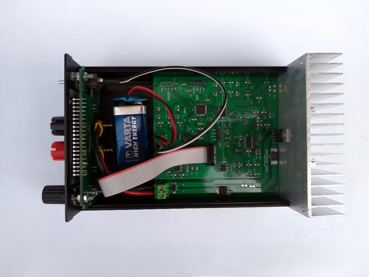
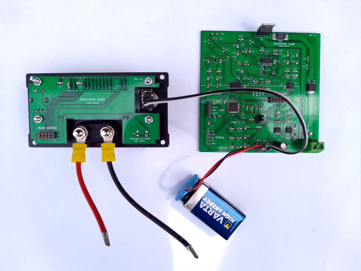
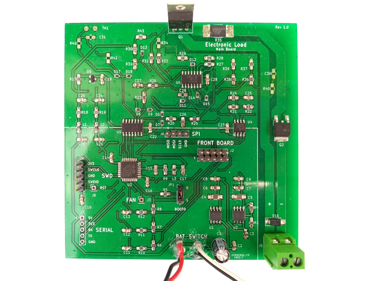
At the moment, it’s only a constant current load, but constant power and constant resistance modes could be implemented in software. The load MOSFET is a BTS141 by Infineon Technologies, which comes with a few handy protection features. It is controlled by an op-amp in the “standard” ground-referenced constant current load topology. A second MOSFET is used to protect the circuit in case of reverse polarity at the inputs.
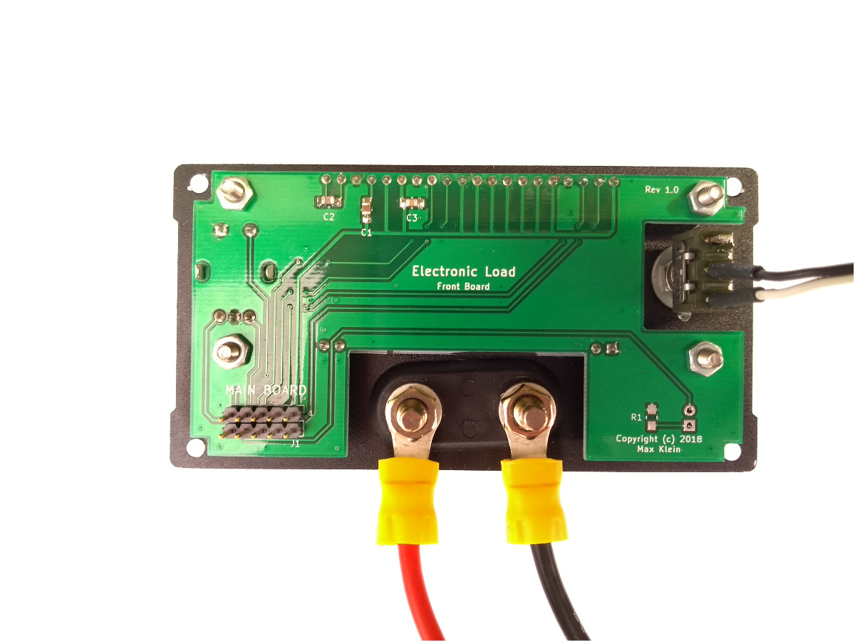
The load is controlled by an STM32L031 microcontroller. The load current can be adjusted with a rotary encoder. An external DAC is used to feed the corresponding voltage to the analog constant current circuitry. The microcontroller measures the actual input current and voltage with an external ADC. The target current, the input current and voltage and the computed input power are displayed on a 16x2 LCD. The microcontroller could also be used to implement stepping of the load current, to test the step response and stability of power supplies.
The components are dimensioned for a load current up to 5 A and an input voltage up to 50 V. The power dissipation is obviously limited to less than 5 A at 50 V (which would be 250 W!). I did not test the maximum power dissipation yet, but it should be possible to improve it by adding a fan to the heat sink.
The project was inspired by this video by Dave Jones (EEVblog).


